
When a tracked remote-control mower loses traction on one side—or stops responding entirely—a failed motor controller is often suspected. But a remote mower motor controller replacement on an older or third-party machine is rarely a simple plug-and-play swap.
A mower owner in France recently contacted MERI about two grey controllers serving the left and right traction motors on an older tracked mower purchased from another supplier. The machine uses two 12 V batteries in series, giving an approximately 24–25 V system. The owner wanted a direct replacement, not a generic controller that would force a complete motor conversion.
This real repair enquiry shows the right way to evaluate the problem: confirm the motor power first, compare every connector and signal wire, and treat the controllers and remote-control conversion box as one matched system.
Quick answer
- Confirm that both traction motors are rated for 24 V and no more than 1,200 W each.
- Do not approve a replacement from voltage, housing shape or wire colours alone.
- For third-party machines, the safer proposal is usually two matched 24 V traction controllers plus one matched remote-control conversion box.
- Final approval requires motor nameplates, connector photos, pinout comparison, mounting dimensions and drive-direction checks.
Why 24 V alone does not prove compatibility
Matching voltage is only the first filter. Two controllers can both be labelled 24 V and still use different signal logic, pin assignments, connector housings, Hall-sensor wiring or direction commands. A controller that looks identical can remain unresponsive—or be damaged—if the small signal connector is wired differently.
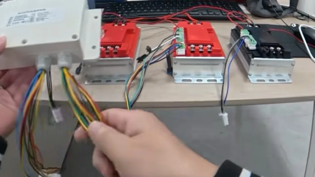
The customer’s photographs showed red and black power cables, blue, yellow and green motor leads, and several smaller connectors. Those colours help technicians trace the existing system, but they are not a universal wiring standard. Every conductor must be identified by function and pin position.
The matched control chain
A tracked mower does not send joystick commands directly to two unrelated motor controllers. The complete signal chain must work together:
Different manufacturers may use different conversion boxes and signal pinouts. That is why MERI recommends replacing the two controllers and their matched conversion box together when the original interface cannot be proven compatible.
Compatibility table for this 24 V repair
| Item | Known requirement | What the owner must confirm |
|---|---|---|
| Battery supply | Nominal 24 V DC | Two 12 V batteries connected in series and the measured pack voltage |
| Motor voltage | 24 V traction motors | Clear nameplate or stamped rating for each motor |
| Controller capacity | 1,200 W per MERI traction controller | Each motor is rated at 1,200 W or below |
| Motor type | Must match the proposed controller | Motor construction, phase leads and sensor wiring |
| Signal interface | Controllers and conversion box must be matched | Small-plug pinout, signal voltage and remote-control logic |
| Physical installation | Secure mounting and adequate heat dissipation | Controller dimensions, mounting holes, cable reach and enclosure space |
| Track direction | Correct left/right response | Forward, reverse and steering direction during controlled commissioning |
What to send before requesting a quotation
Good photos prevent expensive guessing. Send the following before ordering:
- Both old controllers: overall casing, labels, mounting brackets and terminal positions.
- Every connector: front, rear and side views showing pin count, keying and wire colours.
- Battery arrangement: both 12 V batteries, the series jumper and main positive and negative leads.
- Both motor nameplates: rated voltage, wattage, current and any motor-type information.
- Full electrical compartment: one wide image showing controllers, conversion box, fuse or breaker, harness routing and available mounting space.
- Failure description: which track stopped, whether a fuse opens, whether the controller heats up and whether any wiring shows melting or water damage.
MERI can then provide clear controller, conversion-box and connector photos for comparison before the customer commits to the order.
MERI’s compatibility review process
- Review the repair enquiry. We separate a controller fault from possible motor, battery, connector or harness damage.
- Verify power ratings. The nameplates must show 24 V and no more than 1,200 W for each traction motor.
- Map the wiring. Technicians compare power leads, three-phase motor wires, sensor wires, small signal plugs and connector pin positions.
- Check installation fit. Mounting space, heat dissipation, cable length and left/right motor direction are reviewed.
- Define the supply package. If exact compatibility is proven, a limited replacement may be considered. If the old signal interface is uncertain, MERI proposes two matched controllers and one matched conversion box.
- Quote after technical confirmation. Component price and freight are calculated only after the required set and destination are clear.
Controller-only replacement or complete matched set?
A controller-only replacement may work when
- The replacement is the same proven controller specification.
- Connector pinout and signal logic are documented.
- The existing conversion box is confirmed compatible.
- The motor and wiring have passed inspection.
The matched set is the stronger choice when
- The mower came from another manufacturer.
- The original supplier no longer supports the machine.
- The control-box pinout is unknown.
- Both traction controllers require replacement.
- The owner wants one verified control chain instead of combining unrelated components.
For this French enquiry, MERI’s proposed direction is two 24 V, 1,200 W traction controllers plus the matching remote-control conversion box. It avoids assuming that the older third-party conversion unit will communicate correctly with new controllers.
Safety and failure prevention
A new controller should never be used as a diagnostic fuse. If a damaged motor or shorted harness caused the first failure, connecting a new controller without testing can damage the replacement immediately.
- Disconnect and isolate the battery pack before touching power or signal wiring.
- Photograph and label every cable before removing the original controllers.
- Never rely on wire colour alone; confirm function and pin position.
- Inspect insulation, terminals, crimps, fuses and connectors for heat, corrosion, water ingress and mechanical damage.
- Test both motors and the harness for shorts or abnormal resistance before installing new electronics.
- Have a qualified technician commission the system and verify emergency-stop, forward, reverse and steering responses at low speed in a controlled area.
This solution also applies to engine-powered mowers
“24 V controller” describes the traction-control circuit, not the cutter’s main power source. Some remote mowers use a gasoline or diesel engine for cutting while a separate 24 V electrical system powers the left and right traction motors and remote steering.
That means an engine-powered mower can be considered for this repair approach if its traction motors and electrical architecture match the requirements. The engine type does not establish compatibility; the 24 V motor ratings, controller interface, conversion box, connectors and wiring do.
Frequently asked questions
Can I replace a controller just because both units are marked 24 V?
No. Voltage must match, but motor type, rated power, signal logic, connector pinout, Hall-sensor wiring, mounting and drive direction must also be checked.
Why replace the conversion box together with the controllers?
The conversion box translates remote commands for the motor controllers. Different manufacturers may use different pin assignments and signal logic. A matched box and controller set removes one major source of uncertainty.
How do I confirm that my motors are within the 1,200 W limit?
Send clear photographs of both motor nameplates. Each motor must be 24 V and rated at 1,200 W or below before this controller capacity can be considered suitable.
Does MERI guarantee compatibility from photographs alone?
No. Photos are the start of the assessment. Final confirmation may require measurements, wiring information, connector pinouts and controlled commissioning by a qualified technician.
Get a controller compatibility assessment
Send MERI clear photos of both controllers, every connector, the battery wiring and both traction-motor nameplates. We will compare the 24 V system, define the matched component set and prepare a quotation with freight to your country.
Related support resources
Need a mower recommendation for your terrain or project?
Get a Quote