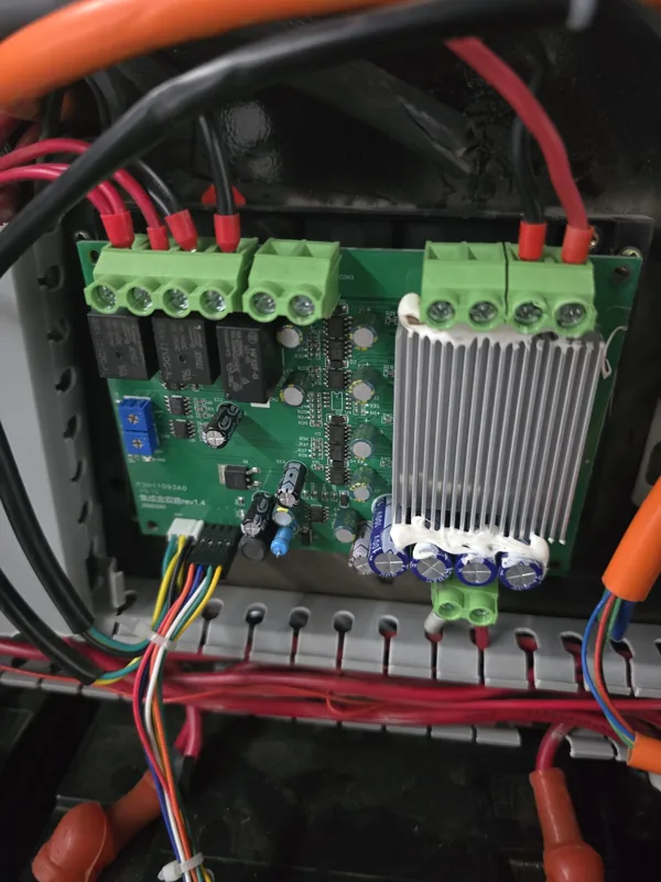
Trace the wiring before ordering a remote mower controller. Start with the module that handles the affected function, then check what else depends on it. In this Swiss parts inquiry, two black boxes appeared to drive the tracks, but the customer's hydraulic lift ran through the green main board. That connection changed what the replacement board needed to support.
What the customer sent
The customer sent three photos of the control electronics and one of the radio receiver. The images showed a green board, black control boxes and a separate receiver. After reviewing the photos and asking where the wires led, we provisionally identified one black driver per track motor, with both drivers connected to the green board.
| Component | What it does | What to photograph |
|---|---|---|
| Radio receiver | Receives commands from the handheld remote | Label and plug leading to the control system |
| Main control board | Passes travel commands to the drivers and can control other functions | Board label and where each harness leads |
| Travel motor driver | Supplies controlled power to a track motor | Driver label, motor connections and command input |
What 24 V and 800 W told us
We asked how the left and right travel motors were connected and whether each motor had its own driver. The customer’s photo showed 24 V and 800 W on a black travel driver. That gave us a starting point for checking the existing drive system. To select a replacement driver, confirm the rated voltage and power on both motor nameplates and compare the labels on both existing drivers.
Then check the motor type, current requirements, feedback wiring, connectors and command signal. For the Swiss quote, the proposed main board needed to send the correct commands to both retained drivers and handle the hydraulic lift. The driver label helped identify the setup, while those connections determined what the board had to support.
The question that narrowed the quote
We asked whether the cutting head used an electric actuator or hydraulic lift. The customer confirmed hydraulic lift and said its controls connected to the green board, with no separate lift control box.
That answer narrowed the quote to one board. A replacement for this machine would need to communicate with the two existing travel drivers and support the original hydraulic lift controls. MERI quoted one control board plus courier shipping and issued a pro forma invoice after the customer chose euros and supplied delivery details. The case ends at the invoice stage, with installation and repair results unverified.
When to replace one module or assess a complete set
- One main board. Consider this when diagnosis points to the board and its replacement matches the retained receiver and drivers, supply voltage, connector pin assignments and lift functions.
- One travel driver. Consider this when testing isolates the fault to that driver. Match the motor type, voltage, rated current, feedback connections and command signal. The 800 W marking visible in the customer’s photo is on the driver. Check the motor nameplate separately.
- A matched set. Assess this if compatible individual modules are unavailable. Check both travel motors, receiver signals, lift control and safety functions such as emergency stop before selecting a system.
A dual drive controller combines two travel channels in one enclosure. That makes it a different system layout from the two separate drivers in this case. If you are considering that change, confirm how the proposed setup will retain the original hydraulic lift. Check the wiring information for the actual unit and machine before installation.
See the controller layouts in the workshop
Watch the MERI demonstration. Use the wiring diagram for your own hardware when checking connections.
Watch the MERI demonstration. Use the wiring diagram for your own hardware when checking connections.
Reference specifications for the two controller layouts
These figures describe the controller options in the supplied technical sheets. The Swiss quote was for a main control board.
| Specification | Single drive | Dual drive |
|---|---|---|
| Dimensions | 250 × 125 × 65 mm | 260 × 140 × 70 mm |
| Listed rated power | 1,200 W | 2,400 W |
| Current limit | 55 A | See the two limits below |
| Overall current limit | — | 190 A |
| Current limit per channel | — | 60 A |
| Listed voltage range | 24–72 V DC | 24–72 V DC |
| Control input | Analog voltage | Analog voltage |
| Functions | Forward and reverse adjustment | Forward and reverse adjustment, travel control, linear actuator control, engine start and stop, and lighting |
| Compatible motor | Square-wave brushless DC motor | Square-wave brushless DC motor |
See the controller replacement compatibility guide for the electrical details to compare across the full control system.
What to send for a parts check
- The symptom. Say whether one track, both tracks or the lift has stopped responding. Include any fault code or indicator behavior you can observe safely.
- The labels and wiring layout. Send the machine model, controller and receiver labels, both motor nameplates and a wide shot showing where the harnesses lead. Include a wiring diagram if you have one.
- The lift type. Say whether the cutting head uses an electric actuator or hydraulics, and identify where its control wiring connects if you know.
Can I keep the old receiver?
Ask the parts team to compare the receiver output and connector pin assignments with the replacement board before ordering.
Does one stationary track prove the driver failed?
It identifies which side to investigate. The driver, motor, supply and harness still need to be checked.
Request a controller parts check
Start with a clear photo of the control compartment and one sentence describing the affected function. MERI can tell you which label or connection to document next and assess whether an individual part or a matched set is appropriate. Request a parts check · MERI Support & Parts
Need a mower recommendation for your terrain or project?
Get a Quote